TW100xx Datasheet
이 문서는 TW100xx 시리즈 제품의 하드웨어 정보를 제공합니다.
Introduction
Key Features
- 4 Port Serial
- Support DHCP IP Acquisition
- Support DNS Query
- Support NTP Time Query
- TCP/UDP Data Communication
- Support Ethernet Data Packing Options
- Support Up to 2Mbps UART Baud Rate
Product Specification
| Item | Specification |
|---|---|
| MCU | STM32F405RGT6 (RAM: 192KByte, FLASH: 1MByte) |
| LAN | W5500 (10/100Mbps Ethernet) |
| UART | 4 Ports (3.3V TTL Level) |
| Console Port | Supported |
| Dimension | TW100MJ: 48.26(W)x61.4(H)x22.0(D), TW100XR:48.26(W)x58.0(H)x15.0(D) |
| Connector | 2.54mm pitch Pin Header. J5: 2x14, J6: 1x14 |
| Input Power | DC 3.3V |
| Power Dissipation | Typical: 100mA, Peadk: 150mA |
| Temperature | Operation: 0 ~ +70 (Celius), Storage: -40 ~ +85 (Celius) |
| Humidity | 10 ~ 80% |
Hardware Specification
Description
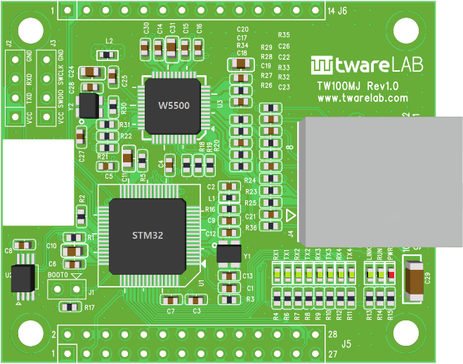
TW100MJ
- RJ45 embedded (Ethernet Transformer inside)
- 2.54 pitch pin header interface (42 pins)
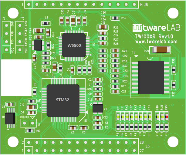
TW100XR
- Ethernet Transformer embedded
- RJ45 is needed on the customer board
- 2.54 pitch pin header interface (42 pins)
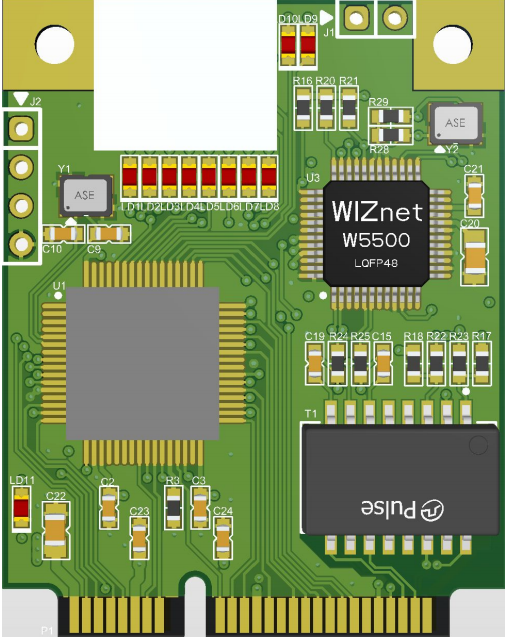
TW100PC
- Ethernet Transformer embedded
- RJ45 is needed on the customer board
- miniPCI interface (52 pins)
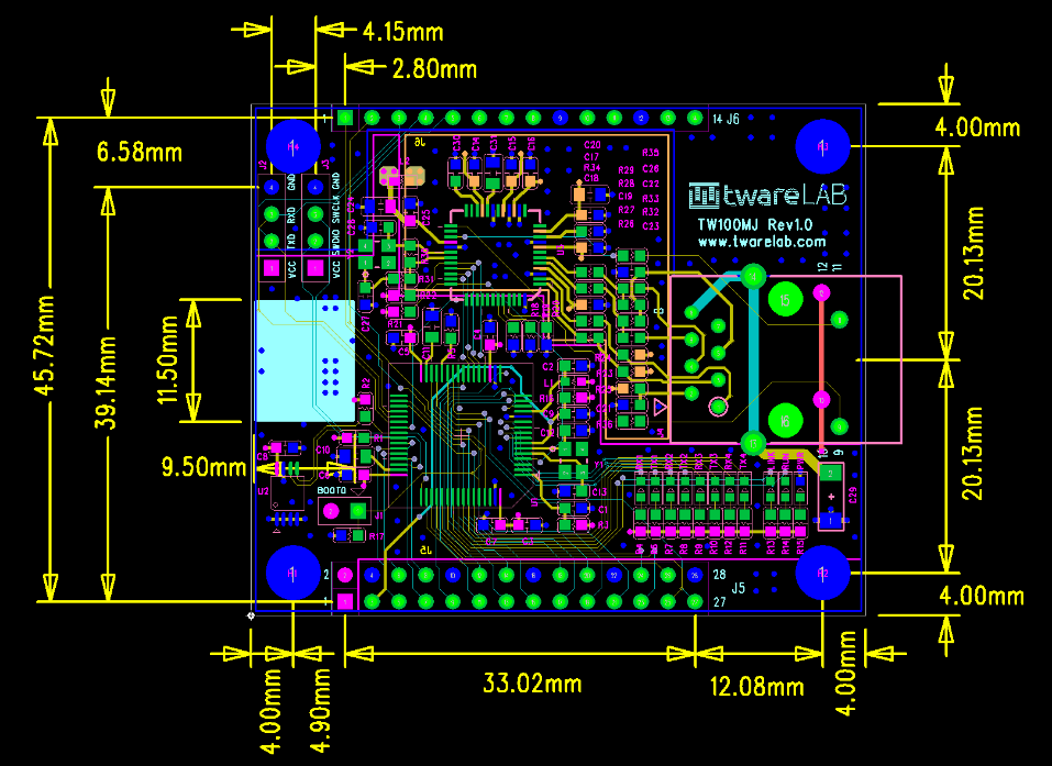
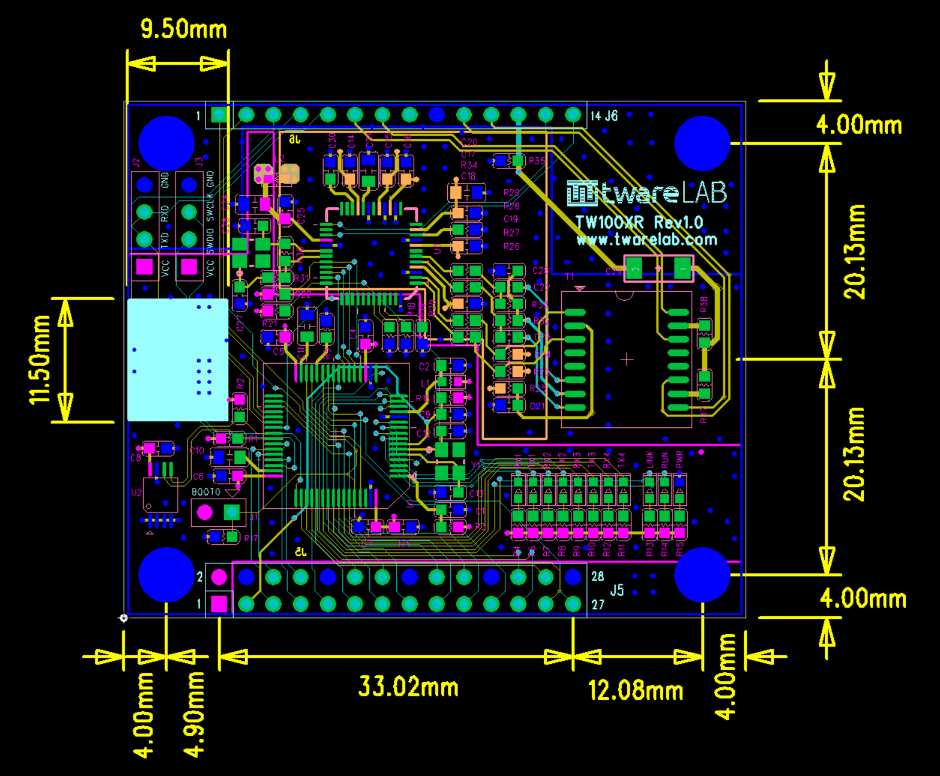
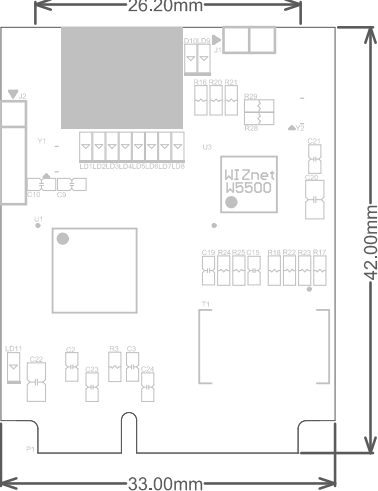
Dimension
TW100MJ
TW100XR
TW100PC
Pin Map
TW100MJ/TW100XR
Header Pin Layout

J5 Connector
| Pins | Signal | I/O | Description |
|---|---|---|---|
| 1 | VCC_3.3 | S | Power 3.3V |
| 2 | VCC_3.3 | S | Power 3.3V |
| 3 | /RESET | I | Board Reset. Active Low |
| 4 | GND | S | Power Ground |
| 5 | UART1_RX | I | UART1 RX Pin. Input. 3.3V TTL Level |
| 6 | UART1_CTS | I | UART1 CTS Pin. Input. 3.3V TTL Level |
| 7 | UART1_TX | O | UART1 TX Pin. Output. 3.3V TTL Level |
| 8 | UART1_RTS | O | UART1 RTS Pin. Output. 3.3V TTL Level |
| 9 | STATUS_1 | O | TCP Connection Status Indicator for Channel 1. HIGH: TCP Disconnected. LOW: TCP Connected |
| 10 | GND | S | Power 3.3V |
| 11 | UART2_RX | I | UART2 RX Pin. Input. 3.3V TTL Level |
| 12 | UART2_CTS | I | UART2 CTS Pin. Input. 3.3V TTL Level |
| 13 | UART2_TX | O | UART2 TX Pin. Output. 3.3V TTL Level |
| 14 | UART2_RTS | O | UART2 RTS Pin. Output. 3.3V TTL Level |
| 15 | STATUS_2 | O | TCP Connection Status Indicator for Channel 2. HIGH: TCP Disconnected. LOW: TCP Connected |
| 16 | GND | S | Power 3.3V |
| 17 | UART3_RX | I | UART3 RX Pin. Input. 3.3V TTL Level |
| 18 | UART3_CTS | I | UART3 CTS Pin. Input. 3.3V TTL Level |
| 19 | UART3_TX | O | UART3 TX Pin. Output. 3.3V TTL Level |
| 20 | UART3_RTS | O | UART3 RTS Pin. Output. 3.3V TTL Level |
| 21 | STATUS_3 | O | TCP Connection Status Indicator for Channel 3. HIGH: TCP Disconnected. LOW: TCP Connected |
| 22 | GND | S | Power 3.3V |
| 23 | UART4_RX | I | UART4 RX Pin. Input. 3.3V TTL Level |
| 24 | UART4_CTS | I | UART4 CTS Pin. Input. 3.3V TTL Level |
| 25 | UART4_TX | O | UART4 TX Pin. Output. 3.3V TTL Level |
| 26 | UART4_RTS | O | UART4 RTS Pin. Output. 3.3V TTL Level |
| 27 | STATUS_4 | O | TCP Connection Status Indicator for Channel 4. HIGH: TCP Disconnected. LOW: TCP Connected |
| 28 | GND | S | Power 3.3V |
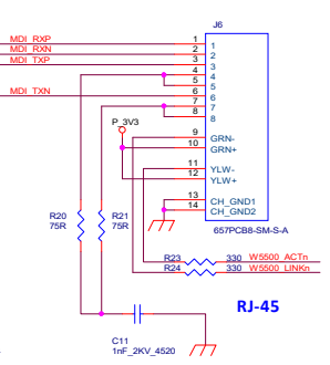
J6 Connector
| Pins | Signal | I/O | Description |
|---|
TW100PC
miniPCI Layout
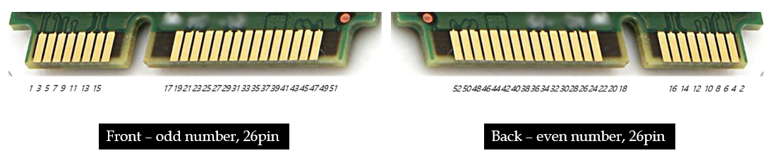
miniPCI Connector
| Pins | Signal | I/O | Description |
|---|---|---|---|
| 1 | VCC_3.3 | S | Power 3.3V |
| 2 | GND | S | Power Ground |
| 3 | NC | ||
| 4 | NC | ||
| 5 | NC | ||
| 6 | NRST | I | Board Reset. Active Low |
| 7 | UART2_CTS | I | UART2 CTS Pin. Input. 3.3V TTL Level |
| 8 | UART2_RTS | O | UART2 RTS Pin. Output. 3.3V TTL Level |
| 9 | UART2_TX | O | UART2 TX Pin. Output. 3.3V TTL Level |
| 10 | UART2_RX | I | UART2 RX Pin. Input. 3.3V TTL Level |
| 11 | VCC_3.3 | S | Power 3.3V |
| 12 | GND | S | Power 3.3V |
| 13 | STATUS_1 | O | TCP Connection Status Indicator for Channel 1. HIGH: TCP Disconnected. LOW: TCP Connected |
| 14 | STATUS_2 | O | TCP Connection Status Indicator for Channel 2. HIGH: TCP Disconnected. LOW: TCP Connected |
| 15 | STATUS_3 | O | TCP Connection Status Indicator for Channel 3. HIGH: TCP Disconnected. LOW: TCP Connected |
| 16 | STATUS_4 | O | TCP Connection Status Indicator for Channel 4. HIGH: TCP Disconnected. LOW: TCP Connected |
| 17 | UART3_TX | O | UART3 TX Pin. Output. 3.3V TTL Level |
| 18 | UART3_RX | I | UART3 RX Pin. Input. 3.3V TTL Level |
| 19 | NC | ||
| 20 | UART3_CTS | I | UART3 CTS Pin. Input. 3.3V TTL Level |
| 21 | UART3_RTS | O | UART3 RTS Pin. Output. 3.3V TTL Level |
| 22 | SW_INPUT | I | SW Input for software reset. Internal Pull-Up. Active Low. |
| 23 | VCC_3.3 | S | Power 3.3V |
| 24 | GND | S | Power 3.3V |
| 25 | Console_TX | O | Uart TX Pin for Console Messages |
| 26 | Console_RX | I | For Future Use |
| 27 | NC | ||
| 28 | NC | ||
| 29 | UART1_TX | O | UART1 TX Pin. Output. 3.3V TTL Level |
| 30 | UART1_RX | I | UART1 RX Pin. Input. 3.3V TTL Level |
| 31 | UART1_CTS | I | UART1 CTS Pin. Input. 3.3V TTL Level |
| 32 | UART1_RTS | O | UART1 RTS Pin. Output. 3.3V TTL Level |
| 33 | NC | ||
| 34 | NC | ||
| 35 | UART4_RTS | O | UART4 RTS Pin. Output. 3.3V TTL Level |
| 36 | UART4_TX | O | UART4 TX Pin. Output. 3.3V TTL Level |
| 37 | UART4_RX | I | UART4 RX Pin. Input. 3.3V TTL Level |
| 38 | UART4_CTS | I | UART4 CTS Pin. Input. 3.3V TTL Level |
| 39 | HW_TRIGGER | I | AT Command Mode Activation Pin. Active Low. Internal Pull-Up |
| 40 | NC | ||
| 41 | NC | ||
| 42 | NC | ||
| 43 | VCC_3.3 | S | Power 3.3V |
| 44 | GND | S | Power 3.3V |
| 45 | /LINK_LED | O | Active Low. LINK LED indicator. Available for only TW100XR |
| 46 | /ACT_LED | O | Active Low. ACT LED indicator. Available for only TW100XR |
| 47 | MDI_RXN | A | Differential Signal to RJ45. Available for only TW100XR |
| 48 | MDI_TXN | A | Differential Signal to RJ45. Available for only TW100XR |
| 49 | MDI_RXP | A | Differential Signal to RJ45. Available for only TW100XR |
| 50 | MDI_TXP | A | Differential Signal to RJ45. Available for only TW100XR |
| 51 | NC | ||
| 52 | AGND | S | Analog Ground |
Reference Schematic